Pocketbike Forum banner

Custom made Cag powered scooter

13K views 54 replies 7 participants last post by  Lord_Loaf  
#1 ·
This is for a scooter that I have playing with and modifying for way too long. It has gone through many different forms of which I will show some pictures of here. I tinkered with some pocketbikes for a little while but I always had a soft spot for upright scooters which is what lead me to this.


As of the making of this post it's finally running again with it being back at using a Cag engine of which I am experimenting with and with to use it as a test bed to set up an electronic ignition that can also be used on my other engines.


If someone could tell me if there is a way to have the attached images displayed in the main post instead of just at the bottom then that would be appreciated.


DISCLAIMER: Although I often come across like I know what I am doing and sometimes I even do, but instead I am often working with ideas that I think are right but can be potentially flawed. This is mostly the case with my custom engine work and while I have done a decent amount of reading there is sometimes false or gaps in my information. I am very open to suggestions and corrections in anything I state.


Now that aside what might be the single most drawn out worklog on here.


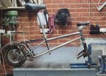
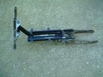
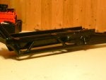
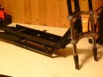
Pic 1 - Bare frame: This is what I started with, it's a childrens scooter, I believe it originally used 16" BMX wheels. I am not sure on the exact date but it was likely back in 2003 some time. At that point I had much more limited skills, knowledge and most of access to equipment.


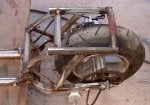
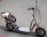
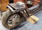
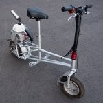
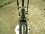
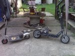
Pic 2 - New wheels: Frame and forks modified to suit the pocketbike wheels.


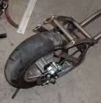
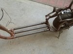
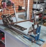
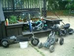
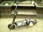
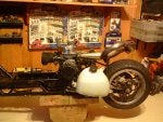
Pic 3 - Frame work: More work to the frame to accommodate the cag engine


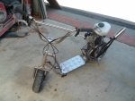
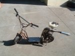
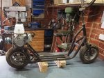
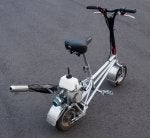
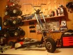
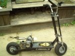
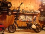
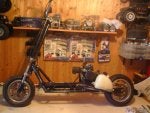
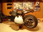
Pic 4 - Stage-1 Done: In a running form with either an original 40 or 49cc Cag engine. The exhaust was a modified OEM pipe.


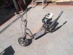
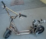
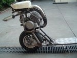
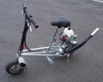
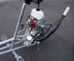
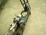
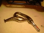
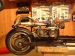
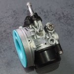
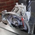
Pic 5 - Stage-2 Done: Custom built engine with 2-piece head, fat boy expansion pipe and a 14mm Dellorto rep carb.
 

Attachments

#2 ·
This ran alright and I was going to make some nice custom parts for it but a deal came up for a Blata rep engine- it was the aircooled 40cc "F1" engine. Apparently rated at 7Hp with the original carb and 9Hp with the 19mm carb I was running.


Pic 1 + 2: Modding the frame to suit the new engine

Pic 3: Further frame work on the engine mounting.

Pic 4: The original mounting of the frame complete. I wasn't happy with how this ended up which will leads to the next post.


At the time I had some doubts about the quoted power figure but wow did I get a wake up call. Initially the slightest bit too much throttle would cause it to do a wheel stand and throw me off. This would happen up or down a hill all the same. I changed from a 6 to a 7 tooth pinion which helped keep the front wheel down but it was still quite scary for me to try and control. If I leaned back it would want to wheel stand, if I leaned forward I couldn't control it properly with the balance and steering. To give an example I own a street luge and I found the Luge quite pleasant compared to how much on edge this made me feel. It was amazing and regardless how dangerous it was it sure loved it.
 

Attachments

#4 ·
To optimistically attempt to control this better I modified the frame further.


Pic 1- Base: The frame was extended and to get some extra rigidity x3 Cro-Mo (4130) pipes were used which made a noticeable difference.

Pic 2 + 3: The rear part of the frame after being modded. The base plate was yet to be extended.


I don't believe I have a photo of how it was after the final assembly.


A little while after this point the ignition coil failed as so many chinese coils do. I couldn't find a replacement anywhere and sadly as a result this was put aside and ignored for something like 10 years under my house rusting away.
 

Attachments

#5 ·
A little over a year ago I decided that even though it would be a big downgrade going back to a Cag engine it would at least run again and give me something to use. And as such this now rusty old scooter was pulled back out and prepared for a downgrade.

Pic 1 - Initial engine mounting: The time this has been sitting around is clearly visible here. In this photo I had fitted the new engine mounting plate has been fitted.

Pic 2 + 3: The engine mounted into place.
 

Attachments

#6 ·
At this stage I was going for the same type of design again but I started to think about how a stand up scooter really isn't practical or comfortable in any sense. I had a friend who had a Go-Ped riot which I sat on and found it to be really comfortable, it was very likely this that caused me to change my plan. I had always suspected that my previous geometry was crap so this time I decided to use something else as a reference. With my tape measure and digital angle gauge I worked out all the basic dimensions of the Go-Ped and from then worked out a plan to make something to match those numbers.

Pic 1: With the original deck temporarily in place the following was fitted: angled lower tubes, RHS cross bar foot pegs, seat pole and the headset tube was shortened.

Pic 2: Upper frame tube added, rear supports mostly done, bottom deck cut away and the left over section removed.


At this stage the only thing left from the original scooter is 2/3 of the head tube and a small part of the original fork in it's middle section. For some reason I didn't take any more progress photos after this so it's going to be a jump to the near end.
 

Attachments

#7 ·
This is how this scooter is as it is right now. It needs to have the kill-switch fitted and likely some other small jobs done but regardless it finally runs again. I was only able to use it for a short time but in that time the stability felt really good, it was very comfortable to use and it performed better than I expected.

I did make some big compromises when making this as I didn't want to fall into the same old trap for me of where I try and make it the best I possibly can and it ends up taking so long that I lose interest or give up. I figure it's better to have some a bit crude than nothing at all.

I also have various photos of internal engine work, other information and engine plans to share but it's getting late over here so I am going to leave it for now and come back.
 

Attachments

#10 ·
Seeings I'm a pretty inquisitive guy I have to ask one main question...

What made you want to go with a reed ported engine for a scooter...?

Mainly what I'm asking is if the scooter is for cruising ,racing or a lil of both...

Reason being is that I had built a scooter with a reed ported engine with CVT transmission and found that I was always fiddling with the reeds and trying to get a combo going that would add longevity to the reeds to no avail...

If I used the scooter for a 10 min blast up to the corner and back it was good....when I rose it 5 miles to my storage unit it would run crappy all the way home if I didn't waste my time flipping the reeds...

Piston ported engines are way more suited for applications where it's gonna be held WOT for periods of 2 miles or more....

The piston ported engine with the full circle crank mod was a sikk revved with sweet lower power and a vicious midrange punch....
 
#11 ·
EPR: thanks, it's been a long while in the works. Now hopefully on top of being nice to use I will also gain some understanding from doing some experimenting with this. The biggest priority at the moment is doing the last minor steps and then just going out and using it. Doesn't matter where so long as it takes me away from home as I really need a change of scenery.


Mrkitty: Nice one, that looks like it would be a blast to use.


Cam2: I initially used one of these engines due to the fact that at the time they were readily available, good value for money, easy to work on, very easy & cheap to source spares for, I had some knowledge on them, were compact and had a centrifugal clutch. As for why I decided to go back to one of these engines, a bit over a year back I figured it was the quickest way out of any option to have my scooter running again and I had lots of parts still.

Now for what might be my most ignorant question yet- can you give some examples of what might of been a good choices for piston ported engines that have centrifugal clutches? Were you thinking along the lines of sourcing a 50cc chainsaw engine?

As for what I want to use it for- I don't want to race, nor use it on the streets. I am going to do mixed riding from gravel paths, concrete flats and other locations. I know it might sound like a dumb idea as it's not really suited to some of the places that I plan to go. But the way I see it it's not like I have a whole lot on the line, I certainly won't be afraid to drop it should I happen to slip due to using small road tyres on a gravel path.

That's a new one to me with the reeds. What went wrong exactly with your reeds? Would they split? What material were yours made of?

One of the things I have been considering to do is to adapt a reed block I made from way back when I was first learning how to use a milling machine. It suits the Blata reed assembly, pics attached. It looks so over the top because I had much more time and energy back then and I was also excited by being able to do milling for the first time, it was fun to machine up and good practice. To make it suit my current engine I would need to make a fairly simple adapter to go between this and the existing reed block mount. This is already half made so it would be quick and easy to finish it. From there I would also need to make an intake manifold which would be a little more annoying but still not too bad to do.

My goal is still to experiment with an electronic CDI ignition which I will hopefully then let me be able to go on to adapt it to use on my Blata Rep engine. This will let my other custom motorbike finally run. So while I might have lots of ideas of what I could do to an engine in the scooter right now I want to balance it so that I don't get too distracted and spend too much time long term on it. Instinctively I want to try lots of different ideas but I need to remind myself to not get completely fixated on it.
 

Attachments

#12 · (Edited)
Here's my homemade scooter...I used a non-reeded type piston ported 2 stroker...

On the reeded engine the reeds would warp and stay open....like I stated before I tried every reed known to man and the ones that lasted the longest believe it or not was the tin reeds.....lol
 

Attachments

#14 ·
Currently it's the middle of winter over here and it's been raining very regularly so I have not been able to use my scooter.

Regardless I did a little bit of work on a concept today. I am using one of the 14mm carbs that are apparently a copy of a Dell'Orto. Also known as a "HP carb". I have been thinking for a while that the harsh transition for the air going into the throat can't be good and about the possibility of fitting a velocity stack.

Removing the choke arm and spring leaves a handy M5 threaded hole as per Pic-1. I figure the engine is very easy to start as is so it shouldn't be an issue. In the quick design I came up with it the velocity stack sits against the various faces and has clearance cut-outs where required, such as whatever that lump is to the middle left of the inside face. I also put in an additional hole to feed the idle control circuit, this is the very small hole directly under the main opening.

After putting in the basic dimensions I then designed it in Solidworks to have a true parabolic transition. Once done I exported it to my 3D printing software, set up the print, saved the setup to a SD card and then gave it to my 3D printer.

Predictably the carb isn't properly concentric but it was close enough such that with some light filing it ended up lining up and fitting quite well. The filter fits into place much the same as it normally would. The overly bright light blue colour just happens to be what's currently loaded in the 3D printer.

When I get a chance I will try this out, conveniently this is very quick and easy to fit and remove as required. it could well be that I am completely misunderstanding something fundamental to the function of the carb that makes this a flawed concept. I don't know, my knowledge and preferences are only to do with fuel injection so this is something new for me.
 

Attachments

#16 · (Edited)
Something along those lines was my plan all along. If this works out then I shall make some small tweaks to the file to make it fit better. From there I am happy to share it to whoever wants it. I have the option of putting it thingiverse, emailing it to people or I can even use a a hidden link to host it my businesses website. I have a lot of bandwidth available as part of my hosting package so even large files are no problem.


It's also quite cheap for me to print. The printing was also didn't take too long with it being under 2 hours. But that was with a course setting and it made completely solid. I could do it again with it partially hollow, a 3 layer thick wall and a finer layer height. A much more subtle colour would be nice too, I have a silver material which looks nice.
 
#17 ·
Outstanding job, been wanting to make a V-stack for the 14mm SHA carb for 10 years. The Polini/14mm Dell has a V-stack that fits inside the stock air filter.
Have a 3D printer helps a lot. Ever think about selling them??
 
#18 · (Edited)
Nice looking part Sam.....One thing though....

 The height of the cutaway portion of the carburetor slide controls how much air is mixed with fuel, the larger the slide cutaway number the leaner the transition off of idle will be.

Also there's a proper way to seal those carbs using an o-ring between the carb and intake......
 
#20 ·
EPR: 3D printers can indeed make things simple. It's unusual for me to use it for any kind of part that's for actual final use. Up until now it has almost completely been used for parts development / test fitting only. I had didn't have any plans to sell them as I am short on time and energy as it is but the possibility is there if it's on a low volume. I already have an online store for auto parts and I send at least half of my products out of the country so it would be very quick and easy to make a listing for these.

Cam2: Even after taking my carb apart into pieces and once again thinking about how it all works I still don't follow what you mean. The bottom of the slide is flat so I don't see which cutaway height you are referring to. But I have yet to read up on doing carb tuning so if that will give me the answer then I don't want to trouble you with more of an explanation.
 
#21 · (Edited)
What I'm basically asking is have you ever wondered why there's a square cutaway open window above the inlet seeings the top of the carb is removeable?

Using a tuned airbox instead of an airfilter works even better with those carbs too....


In reply to the slide cutaway question....Those carbs are more comprehensive than you realize....There's a master tuning pack that has assorted slides with different type cutaway n such to fine tune those carbs in addition to inlet reducers needle types and jetting...
 

Attachments

#26 ·
What I'm basically asking is have you ever wondered why there's a square cutaway open window above the inlet seeings the top of the carb is removeable?

I did previously try and work out why there was that cavity above the main 14mm intake hole. After taking the carb apart and seeing that there was no direct path for the air to go from there to anywhere else I figured that it was only there to simplify and save material during the die casting process. Unless you mean the air getting between the small clearances between the housing sides of the slide then I still don't understand how it does anything. I thought you might be referring to the central brass fuel tube but that's closed at the top as well so I am left seriously confused. No matter how much I dislike them I need to do some reading to learn more about carbs. Do I need to match that top opening shape directly to the velocity stack or can I just have a partial cut-out to feed air to that part?


In reply to the slide cutaway question....Those carbs are more comprehensive than you realize....There's a master tuning pack that has assorted slides with different type cutaway n such to fine tune those carbs in addition to inlet reducers needle types and jetting...
That makes sense, thanks for posting the pic. I was wondering how it was that there was only a main jet and a mechanical stopper for the slide closing and nothing else. No wonder I was confused. I currently have the flat bottom / #1.


I've never seen a program write itself and feed itself measurements in order to bring the part to life and for sure it takes better than an hour
I was originally only going to use the 3D printed part as a test fit but otherwise machine it manually. But then I had a think about it and figured it should be fine in the 3D printed PLA material. But it could really use some work with sandpaper to smooth the transition of the air going in.

When I am making something I would normally measure it up and design it for either choice. I may use CAD for both options depending on the part so it would depend on that and the time it would take for machining if I choose that. As for the 3D printing I would need to export the CAD file into my printing program, a few quick settings made, exported to a SD card and then plugged into my 3D printer. From there after choosing the file I can usually leave it alone. So while it did take close to 2 hours to print I was off doing work elsewhere. Printing the part can potentially also have a big bonus in that I can quickly make some changes to the CAD file and then set it to print again, all without taking much of my time. So it comes down to the part and it's application.


I completely agree in the fact that it allows for things that would normally not be practical to machine up. The image below is the 3D model of a part that I designed and printed off for a friend during the week. This one could of been made using a combination of machining and fabrication but it would not of been worth it.
 

Attachments

#23 ·
no way the 3d printer is the way to go you just load the cad file into the slicer and hit start I like to keep an eye on it untill layer 3 then I go find something better to do I will check up on it every so often some times my printer will mess up but once you get the hang of setting it up for the most part you just pull the part off and it's ready to use
 
#24 · (Edited)
I've never seen a program write itself and feed itself measurements in order to bring the part to life and for sure it takes better than an hour

Even with the fastestt 3D printing technology, a part will not take more than a day or two to design, and that couple days, again, is with a massively large part using FDM or FFM technology.

The advantage of 3D printers is that the complexity and types of parts they can build is dramatically higher than that of the parts that can be built on a CNC machine. Which 95% of my designs can be...
 
#25 ·
No you're right you have to design the part I use tinkercad but there's tons of other software out there

Here is a folding drone I just printed out it's a work in progress

I think you whould really enjoy 3D printing and you could make some really cool stuff with your past experience...
 

Attachments

#28 · (Edited)
Looks good, well done.


UPDATE: Previously I decided to build a second spare engine so as to reduce any possible down-time with my scooter as much as possible. To go about this I had a new case / housing set arrive 2-3 weeks ago that I had ordered from Aliexpress. At the time I quickly noticed that while similar it was made from a different casting mould. Looking closer I discovered what seems to be the insignia from a different company. Unlike my other old cases this has "888" on each housing. In some ways quality is better and in others worse.

The job I did on the weekend is to do some Blueprinting, mods and a little assembly to this new housing. To do the Blueprinting I would align the faces and take the lightest cut possible to clean up and increase the accuracy of the faces. For example making sure were relevant the faces are indeed parallel.


Pic 1+2 - Outer faces: The surfaces of the outer faces were seriously rough with heavy chatter marks. Pictured before and after doing a light surfacing cut. The photos don't show it well due to the reflection of my lighting system.


Pic 3- Intake face: Normally this surface is not at all critical, however I found that unlike my other housings this wasn't parallel to the face of where the barrel bolts on but rather on a small angle to it. This could of caused some complications in trying to clamp each housing for some of my other machining work. To avoid that I did the quick and easy job of re-cutting the face. To make it parallel to the chamber to barrel face I pushed that part of the housings down against some parallel bars.


Pic 4 - Pin alignment: Using my edge finder to check the alignment of the pin holes relative to the center point between both sides of the case. Unlike the last housing I checked it was actually not too bad. If it wasn't right I could of re-aligned the holes by enlarging from 5 to 5.5mm using a milling cutter and reamer to then make some new 5.5mm dowels out of linear rod. If I actually would of been bothered to do so is another question.


Pic 5 - Barrel face: This face where the barrel gasket seals against had a crap finish. I could feel with my finger nail I could feel a small step between two passes of the previous milling. Using the same method as the intake face it was cleaned up with the smallest cut possible. Also visible are two different relief cuts to allow better airflow into the boost port(s).


Pic 6 - Bottom mounts: Predictably these were pretty bad. Pictured half way through the cut to show how far off they where. By fixing these up it guarantees the upright alignment of the engine. Secondly when the engine mounts don't all evenly touch the surface of mounting plate in the frame it causes stress to be put on the housings when the bolts are tightened by due to some feet being pulled down more than others.


Other jobs that I was able to do that aren't pictured:

- Re-cutting the top engine mounting point to make sure it's parallel. This is important as it's what I use to align the engine into my frame.

- I checked the alignment of one end of the crank to the other. They where parallel to each other but one side was 0.3mm off-centre to the other. Even though I know this is bad to have I left that alone because it would be way too much trouble to do anything about it.

- Assembly of the bottom end with these reworked cases, this time without a full circle crank.
 

Attachments

#32 ·
They have really low mileage engines for sale on the internet with free shipping cheap and come with 3 year warranties,,,,

Its alot faster of a process than youre gonna go through especially if you kicked a rodbearing in that puppy and ran it for any substantial time....The oil filter aint gonna help ya much if thats the case........

Youre in for a full, total and pretty costly rebuild otherwise......

Good Luck
 
#36 ·
I have been meaning to do an update for a while now. I was able to take this for a decent ride for the first time. It was very stable but needed heavier clutch springs. After about 45 minutes it stopped dead. Pulling a torch out of my pocket I discovered that the housing of the carby itself had broken off at the flange. I figure it's the combination of too much engine vibrations from the inbalance and over-tension of the carby mounting bolt. Conveniently the spring loaded tensioner lets me take the chain off quickly and easily so I will able to push it without any drag and I was back at my car after 10 min of pushing.

I was already in the process of building another bottom end but this time (this time without making the mistake of using a full circle crank) and as such it didn't bother me much when I had this breakage. Pulling the engine apart I did a little more work to the barrel and also prepared a second barrel I had available. I was able make some good progress but when I was doing one final reference cut on the bottom flange side of my original barrel the milling cutter grabbed. This pulled it out of the vice and tore a section of flange out where it's meant to bolt down. I was quite irritated with that development. So much for having a spare prepared barrel on hand.

Other work I did were some piston mods in cutting a small amount of material off the crown of the piston. It looks like a lot but is only about 1 gram worth. This changes the shape from a dome to instead a taper for the outer part. I did all my pistons at once while I had the lathe set up. I believe this gives big advantages- the first being that all of my pistons now have the same pin to dome height which will mean my port timing won't change with a piston change. Secondly it optimises the combustion chamber to have gentle taper in the quench zone from the outer edge opening up a little once it reaches the main chamber. Before the shape of the piston and dome was such that it would trap a donut shaped circle of gases around the outer edge of the chamber under compression. If that makes any difference or not I don't know but it does make it a much more accurate process to measure the minimum squish clearance.

The scooter was fully reassembled with a new carby fitted and while it would run it would only do so with some engine starting compound in the intake, so the carby just isn't doing it's job. I have since tried taking it apart to see if I could find anything wrong with it and even changing the jet over from my old broken model but no it does the same thing. I also checked the fuel flow and that the jets were all clear. Next weekend I will aim to put a completely different carby on and see if it makes a difference. If anyone has any tips then I will gladly receive it. Once again I really hate carburettors.

Another update I have is I finished my Blata-rep V-block reed cage adapter and the matching parts to suit. I shall cover that in another post. I am happy with how it turned out. Of note the carby problem I have happens with both my old and new intake system so it's not the issue.
 

Attachments